Printable Weld Symbol Chart
adminse
Apr 07, 2025 · 8 min read
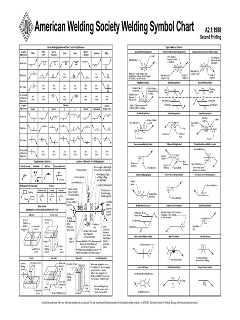
Table of Contents
Decoding the Language of Welding: A Comprehensive Guide to Printable Weld Symbol Charts
What if understanding complex welding symbols was as easy as glancing at a readily available chart? Printable weld symbol charts are the key to unlocking efficient communication and ensuring consistent, high-quality welds across all projects.
Editor’s Note: This article on printable weld symbol charts provides a comprehensive overview of their purpose, interpretation, and practical applications. Updated with the latest industry standards, this guide serves as a valuable resource for welders, engineers, and anyone involved in fabrication and construction.
Why Printable Weld Symbol Charts Matter:
Welding is a critical process in numerous industries, from construction and manufacturing to aerospace and automotive engineering. Misunderstandings in weld specifications can lead to costly rework, project delays, and potentially dangerous structural failures. Printable weld symbol charts act as a standardized visual language, ensuring everyone involved—welders, inspectors, engineers, and designers—is on the same page regarding weld requirements. This eliminates ambiguity, improves communication, and ultimately contributes to enhanced safety and productivity. Their portability and accessibility make them invaluable in the field, the workshop, or the classroom.
Overview: What This Article Covers:
This article will delve into the intricacies of weld symbols, explaining their components and how to interpret them effectively. We'll explore the different types of weld symbols, the significance of each element, and provide practical tips for creating and using your own printable charts. Furthermore, we will discuss the importance of adhering to relevant welding codes and standards, highlighting the critical role of these charts in ensuring project success.
The Research and Effort Behind the Insights:
This comprehensive guide is based on extensive research, drawing from recognized welding standards such as AWS D1.1 (Structural Welding Code—Steel) and ISO 2553 (Welding—Symbols for welding). The information presented reflects current best practices and incorporates insights from experienced welders and engineering professionals. Each element of the weld symbol is meticulously explained with illustrative examples to ensure clarity and understanding.
Key Takeaways:
- Definition and Core Concepts: A detailed explanation of the standard weld symbol and its constituent parts.
- Reference Lines and Arrows: Understanding the directional indicators within the weld symbol.
- Basic Weld Symbols: Identification and interpretation of common weld types (e.g., fillet welds, groove welds, spot welds).
- Supplementary Symbols: Deciphering additional symbols that provide further details on weld preparation, dimensions, and other specifications.
- Creating Your Own Printable Chart: Practical steps to develop a customized chart for your specific needs.
- Industry Applications and Standards: How these charts are used in various industries and how they align with relevant codes.
Smooth Transition to the Core Discussion:
Now that the importance of weld symbol charts is established, let’s explore the detailed structure and interpretation of these crucial visual aids, focusing on how to effectively use and create your own printable versions.
Exploring the Key Aspects of Printable Weld Symbol Charts:
1. Understanding the Basic Weld Symbol:
A standard weld symbol typically includes a reference line, an arrow, and a basic weld symbol.
- Reference Line: This horizontal line forms the base of the symbol. Dimensions and other specifications are placed above or below this line, depending on their nature.
- Arrow: The arrow indicates the location of the weld on the component. It points towards the member receiving the weld. The arrowhead touches the reference line.
- Basic Weld Symbol: This represents the type of weld being used (e.g., a square for a fillet weld, a triangle for a groove weld). Different symbols denote different weld geometries and configurations.
2. Location and Application of Weld Symbols:
The position of the symbol above or below the reference line dictates where the weld is applied.
- Above the Reference Line: Indicates that the weld is applied to the arrow side of the joint.
- Below the Reference Line: Indicates that the weld is applied to the other side of the joint (opposite to the arrow side).
3. Supplementary Symbols:
Numerous supplementary symbols provide detailed information beyond the basic weld type. These include:
- Weld Dimensions: Symbols and numerical values specify the leg length of fillet welds, the size of groove welds, and other critical dimensions.
- Weld Types: Specific symbols denote different types of groove welds (e.g., V-groove, U-groove, J-groove), fillet welds (e.g., convex, concave), and other specialized weld configurations.
- Weld Preparation: Symbols describe the required weld preparation, such as bevel angles, root opening, and other crucial details.
- Finishing Symbols: Indicate the required finish for the weld, such as grinding, chipping, or other surface treatments.
- Field Weld Symbols: Specify that the weld is to be completed in the field rather than in the shop.
4. Creating Your Own Printable Weld Symbol Chart:
Creating a customized printable chart requires careful planning and attention to detail. Here's a step-by-step guide:
- Gather Information: Compile a list of the most commonly used weld symbols in your specific application.
- Choose a Template: Use a spreadsheet program (like Excel or Google Sheets) or a dedicated graphics program (like Adobe Illustrator or CorelDRAW) to create the layout.
- Add Symbols: Insert the relevant symbols using the chosen software. Ensure accuracy and clarity.
- Include Explanations: Add clear explanations of each symbol and its meaning to provide comprehensive guidance.
- Add Examples: Include visual examples of each weld type to aid understanding.
- Print and Laminate: Print multiple copies for easy access. Laminating the chart will provide durability and protection.
Closing Insights: Summarizing the Core Discussion:
Printable weld symbol charts are far more than just visual aids; they are essential tools for clear communication and accurate execution in the welding process. By mastering the interpretation of these charts, welders, engineers, and all project stakeholders can ensure consistent quality, reduce errors, and significantly improve safety.
Exploring the Connection Between Welding Codes and Printable Weld Symbol Charts:
Welding codes and standards (like AWS D1.1 and ISO 2553) provide the framework for consistent and safe welding practices. Printable weld symbol charts are inextricably linked to these codes. They act as a visual representation of the specific requirements outlined in the codes. The symbols used in the charts adhere to the established standards, ensuring uniformity and preventing misinterpretations.
Key Factors to Consider:
- Roles and Real-World Examples: Weld symbol charts are used by welders, inspectors, designers, and engineers to ensure that the welds meet the required specifications. Consider a large-scale construction project where a detailed weld symbol chart is vital for coordinating different crews and ensuring the structural integrity of the entire project.
- Risks and Mitigations: Incorrect interpretation of weld symbols can lead to faulty welds, potentially resulting in structural failure. Using a standardized and easily understood chart significantly mitigates this risk.
- Impact and Implications: The use of consistently applied weld symbols improves productivity by reducing rework, improves safety by reducing errors, and improves communication between all project personnel.
Conclusion: Reinforcing the Connection:
The relationship between welding codes and printable weld symbol charts is symbiotic. The charts act as an essential bridge between the technical language of the codes and the practical application of welding. By using these charts, professionals can translate complex technical requirements into easily understandable visual instructions, fostering a safer and more efficient working environment.
Further Analysis: Examining Welding Standards in Greater Detail:
Different countries and organizations employ specific welding standards (like AWS, ASME, ISO). These standards detail acceptable welding procedures, materials, and inspection methods. Printable weld symbol charts should always conform to the relevant standard adopted for a given project. Understanding these standards is vital for correct chart interpretation and application.
FAQ Section: Answering Common Questions About Printable Weld Symbol Charts:
- What is a weld symbol chart? A weld symbol chart is a visual aid that uses standardized symbols to communicate detailed weld specifications.
- Why are they important? They ensure clear and unambiguous communication between all parties involved in the welding process.
- Where can I find printable weld symbol charts? You can find pre-made charts online or create your own using software like Microsoft Excel or dedicated graphic design software.
- What information should a weld symbol chart include? It should include the basic weld symbols, supplementary symbols, and clear explanations of their meanings, along with visual examples.
- Are there specific standards for weld symbols? Yes, the symbols are standardized according to codes such as AWS D1.1 and ISO 2553.
Practical Tips: Maximizing the Benefits of Printable Weld Symbol Charts:
- Maintain Accuracy: Ensure that the symbols on your chart accurately reflect the relevant welding standards.
- Provide Clear Explanations: Clearly define each symbol and its meaning. Consider using both text and visual examples.
- Use High-Quality Materials: Print the chart on durable paper or laminate it for longevity.
- Keep it Accessible: Place the chart in a visible and readily accessible location for all project personnel.
- Regularly Review: Periodically review and update your chart to reflect any changes in standards or practices.
Final Conclusion: Wrapping Up with Lasting Insights:
Printable weld symbol charts are indispensable tools for efficient welding operations. By understanding their structure, interpretation, and applications, professionals can enhance communication, improve accuracy, and contribute to safer, more productive welding practices. These charts are a cornerstone of effective welding project management and ensuring the creation of high-quality, durable welds. The investment in creating and utilizing these charts significantly outweighs any potential costs associated with errors or rework due to miscommunication.
Latest Posts
Latest Posts
-
Pug Printable Coloring Pages
Apr 08, 2025
-
Ptcb Practice Exam Printable
Apr 08, 2025
-
Psu Football Schedule Printable
Apr 08, 2025
-
Psu Football Schedule 2024 Printable
Apr 08, 2025
-
Psalms 23 King James Version Printable
Apr 08, 2025
Related Post
Thank you for visiting our website which covers about Printable Weld Symbol Chart . We hope the information provided has been useful to you. Feel free to contact us if you have any questions or need further assistance. See you next time and don't miss to bookmark.
